How to Test Data Center Link Solution by Optical Power Meter?
In this era of information industrialization, both the application of emerging technologies and the construction of smart cities are inseparable from the basic network. The construction of the basic network is based on the site, active terminals and interconnected devices, as well as the basic interconnection channel for building the network–the wiring system. The wiring system needs to be installed and installed on site, which is susceptible to environmental, product quality, installation process and other factors, and is the most important link to determine the quality of network transmission. The reliability of the wiring system depends not only on the quality supervision in the project, but also on the final level and on-site acceptance testing. So how to test the fiber optic link solution by optical power meter?
Fiber Link Test
40G Fiber Link Solution:
A standard MPO/MTP link consists of two MPO jumpers at both ends, two MPO adapters, and an MPO pre-connected trunk cable. In TIA-568-C.0-2009B.4, for parallel multi-channel transmission, A and B are given. In order to ensure the compatibility and unity of the link, it is convenient to construct and maintain, especially the MPO jumper that is frequently plugged and replaced. In the 40G/100G cabling system, mode B is used more often. The 40G and 100G channels have different numbers, but the transmission link model is the same, and both use the MPO/MTP interface for end-to-end transmission. Therefore, we take 40G single-channel transmission as an example. Pay attention to the port type of pre-connected fiber optic cable and jumper when testing – there are guide pin (male) and no guide pin (female).
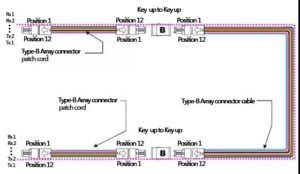
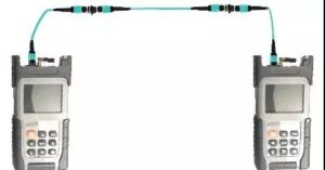
Tested Fiber Link: MPO fiber link model with no lead pin (female) at both end
![]()
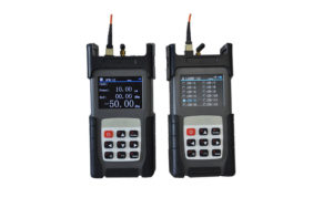
Tools: MPO/MTP Optical Power Meter. TL3224 MPO/MTP Optical Power Meter and TL3124 MPO/MTP Optical Light Source is an Optical Test Solutions especially designed for Data Center on site testing. The MPO/MTP Optical Power Meter and MPO/MTP Optical Light Source could be applied in pair to test the insertion loss for MPO/MTP Patch Cord Insertion Loss, Polarity Condition, etc. it support data storage, threshold analysis as well as data uploading, is much more efficient compared with traditional light source and power meter.
Procedure:
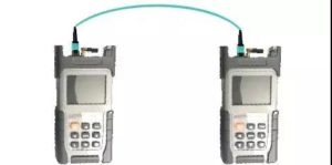
1) Set the benchmark:
Use MPO-MPO (male-male) jumper to short the MPO light source and MPO optical power meter, first select the polarity corresponding to the jumper on the instrument, then press the reference value (set reference) setting button, then the optical power meter Record the initial optical power value received.
2) Join MPO-MPO (male-male)
Keep the jumper connection of the light source end unchanged, only remove the jumper plug of the optical power meter, and then add a quality qualified, correct polarity MPO-MPO (male-male) test jumper to the optical power meter (should be Pass the test).
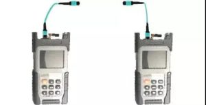
3) Testing
Place the instrument on the test main interface, insert the test jumpers on the light source and the optical power meter into the two ends of the tested link, press the test button, and the instrument will give the pass/fail result after a few seconds (or give a similar prompt / As shown, press the store button to name and save the test results. Continue to test the next MPO fiber.
Conclusion
The original 10GMPO test model is no longer suitable for future 40G/100G test needs. The LC interface’s light source and optical power meter lead to a significant increase in the number and time of MPO fiber link tests. A 12-core MPO trunk link requires nearly 10 minutes of complete testing. Therefore, MPO/MTP optical power meter is indispensable for data center application.
SFP vs SFP+: What’s the Difference and Which One Should You Use?

Step-by-Step Guide for Installing and Removing SFP Transceivers