Product show: Optical Time Domain Reflectometer
Fiber optic cable testing is an important technical means for cable construction, maintenance, and repair. The use of OTDR (optical time domain reflectometer) for fiber connection loss measurement is currently a more effective method. The OTDR is a precision optoelectronic integrated instrument made by Rayleigh scattering and Fresnel reflection caused by light transmission in optical fiber. It is widely used in the maintenance and construction of optical cable lines. Measurements such as fiber length, fiber transmission attenuation, joint attenuation, and fault location.
How does it work?
The OTDR test is performed by transmitting a light pulse into the fiber and then receiving the returned information at the OTDR port. When a light pulse is transmitted within an optical fiber, it can scatter and reflect due to the nature of the fiber itself, connectors, joints, bends, or other similar events. Part of the scattering and reflection will be returned to the OTDR. The useful information returned is measured by the OTDR detectors as a time or curve segment at different locations within the fiber. The distance can be calculated from the time it takes to transmit the signal to the return signal, and then determine the speed of the light in the glass material.
![]()
Main performance indicators of OTDR
Wavelength:
The wavelength refers to the wavelength of the laser light emitted by the OTDR laser, and 1310 nm or 1550 nm is selected as needed. When performing fiber testing before the system is turned on, the selected wavelength should be the same as the wavelength used by the system being turned on. The longer the wavelength, the weaker the Rayleigh scattering optical power, so the 1310 nm pulse produces a Rayleigh scattering trajectory pattern that is higher than the 1550 nm pattern. Long-distance selection of 1550nm wavelength is suitable, because in the long-distance test, the 1310nm wavelength attenuation is large, the laser pulse emitted by the laser will become very weak at the end of the fiber to be tested, which is greatly affected by noise, and the resulting trajectory map will be not ideal. In the high wavelength region (above 1500 nm), although Rayleigh scattering will continue to decrease, an infrared attenuation (or absorption) will occur. Conduct a full-length fiber backscatter signal curve test, preferably 1550nm wavelength. The fiber length and joint loss values measured at the two wavelengths are basically the same, but the 1550 nm wavelength makes it easier to find out if there is excessive bending on the fiber line.
Dynamic Range:
Dynamic range is one of the main performance indicators of OTDR, which determines the maximum measurable length of the fiber. The larger the dynamic range, the better the curve line type and the longer the measurable distance. There are two main ways to increase the dynamic range: to increase the initial backscatter level and reduce the noise level and to affect the initial backscatter level is the scan average time.
The blind zone:
The blind zone, also known as the dead zone, is affected by the Fresnel reflection. The OTDR curve cannot reflect the state of the fiber state within a certain distance. This phenomenon occurs mainly because the Fresnel reflection signal on the fiber link makes the photodetector saturated, which requires a certain recovery time. The dead zone can occur in the live knot in front of the OTDR panel or in other areas of the fiber link that have Fresnel reflections. The size of the blind zone determines the measurement accuracy of the OTDR, so the smaller the blind zone, the better. The dead zone increases with the increase of the pulse width. Although the increase of the pulse width increases the measurement length, it also increases the measurement dead zone. Therefore, when testing the fiber, we use the measurement of the OTDR fiber accessory and adjacent event points. Narrow pulses, while wide pulses are used when making measurements on the far end of the fiber. The smaller the pulse width and the shorter the dead zone, the shorter the pulse and the smaller the dynamic range. Therefore, the pulse width should be compromised between the blind zone and the dynamic range.
Introduction to GPON Optical Modules and Their Classification Standards
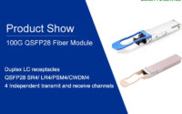
100G Fiber Optic Transceivers — QSFP28