Professional Insights into MPO Jumper Parameter

In the realm of high – speed data transmission and fiber – optic communication, MPO (Multi – fiber Push On) jumpers have emerged as a pivotal component. Their ability to support high – density and high – speed connections makes them indispensable in modern data centers, telecommunications networks, and various other applications. This blog will delve into the key parameters of MPO jumpers, explaining their significance and how they impact the performance and suitability of these jumpers for different scenarios.
Fiber Core Count
The fiber core count is one of the most fundamental parameters of an MPO jumper. Common core counts include 8, 12, 16, and 24, with 12 – core and 24 – core being particularly prevalent.
Core MPO Jumpers
8 – core MPO jumpers are an excellent choice for systems using two – core and eight – core fiber transceiver technologies. They ensure 100% utilization of the fiber in an eight – core transceiver system, without the need for additional conversion equipment. For example, in 40G and 100G line deployments, where eight – fiber transceivers are commonly used, 8 – core MPO jumpers can provide a direct and efficient connection. Additionally, 8 – core branch jumpers can be easily routed to the ports of common switch line cards, as most line cards have a port number divisible by four, allowing for four – way LC duplex connections.
12 – Core MPO Jumpers
12 – core MPO jumpers have a higher fiber – use density per connector compared to 8 – core ones. They are well – suited for existing large – scale 12 – core fiber MTP deployments. However, when connecting to a port that only requires 8 fibers, 4 fibers may be left unused, which could lead to increased cabling costs and insertion losses if conversion modules or branch jumpers are used to fully utilize the fibers.
24 – Core MPO Jumpers
24 – core MPO jumpers are typically used in 100GBASE – SR10 links. They offer a seamless upgrade path for 10G, 40G, and 100G networks. For instance, when upgrading a 40G network, a 12 – core MPO cable may waste 4 fibers, while a 24 – core MPO cable can provide a 1:3 configuration without fiber waste. Moreover, 24 – core MPO cables can support 100G fiber modules, which is not yet available for 12 – core MPO in some cases. They also occupy less space compared to 12 – core MPO cables.
Insertion Loss
Insertion loss is a critical factor affecting the performance of fiber – optic networks. It refers to the loss of optical power when light passes through an MPO jumper. Lower insertion loss indicates better transmission performance.
Typical Values
For MPO jumpers, the typical insertion loss values vary depending on the type of fiber (single – mode or multi – mode) and the quality of the jumper. Generally, multi – mode MPO fiber jumpers should have an insertion loss of less than 0.6 dB, while single – mode MPO fiber jumpers should have an insertion loss of less than 0.75 dB. High – quality single – mode and multi – mode MPO fiber jumpers often aim for an insertion loss of less than 0.35 dB.
Impact on Performance
In high – speed data transmission applications, such as 100Gbps or higher – rate networks, even a small increase in insertion loss can lead to significant signal attenuation, resulting in data errors and reduced network reliability. Therefore, when selecting an MPO jumper, it is crucial to choose one with low insertion loss to ensure stable data transmission.
Return Loss (Echo Loss)
Return loss, also known as echo loss, measures the amount of light reflected back from the connector interface. A higher return loss value indicates less reflected light and better performance.
Measurement and Requirements
Return loss is typically measured using methods such as the OCWR (Optical Continuous Wave Reflectometer) method or the OTDR (Optical Time – Domain Reflectometer) method. For MPO connectors, the return loss requirements vary depending on the end – face type. For example, APC (Angled Physical Contact) end – faces usually require a return loss of ≥ 50 dB, while UPC (Ultra Physical Contact) end – faces require a return loss of ≥ 50 dB for the MPO end and ≥ 60 dB for the branch – end connector.
Significance in Applications
In applications where signal reflection can cause interference, such as high – speed data centers and telecommunications networks, a high return loss is essential. Excessive reflection can lead to signal distortion, reduced signal – to – noise ratio, and decreased system performance. Therefore, MPO jumpers with high return loss are preferred in these scenarios.
Flame – Retardant Rating
The flame – retardant rating of an MPO jumper’s cable sheath is an important consideration, especially in environments with high fire – safety requirements, such as ceilings and raised floors.
Common Flame – Retardant Materials
The cable sheaths of MPO jumpers can be made of various materials with different fire – resistance properties, such as PVC (Polyvinyl Chloride), LSZH (Low – Smoke Zero – Halogen), etc. LSZH materials are often preferred in enclosed spaces because they do not release toxic and corrosive substances when burned, providing better protection for people and equipment in case of a fire.
Choosing the Right Rating
When purchasing an MPO fiber jumper, it is necessary to check its flame – retardant rating and select a jumper that meets the requirements of the installation environment. For example, in areas with strict fire – safety regulations, jumpers with a higher flame – retardant rating should be chosen.
Polarity
Polarity refers to the arrangement of fiber cores at the two ends of an MPO jumper. There are three common polarity types: Type A (Straight – Through), Type B (Crossed).
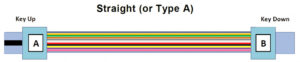
Type A (Straight – Through)
In Type A jumpers, the fiber core arrangement at both ends is the same. That is, core 1 at one end corresponds to core 1 at the other end, and core 12 corresponds to core 12. The key orientations at the two ends are opposite, with key up corresponding to key down. This type is suitable for applications where a direct connection is required, such as simple point – to – point connections.
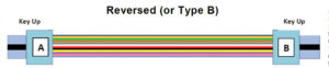
Type B (Crossed)
Type B jumpers have opposite fiber core arrangements at the two ends. Core 1 at one end corresponds to core 12 at the other end, and vice versa. The key orientations at the two ends are the same. This type is often used in applications where signal reversal is needed.
Transmission Distance
The transmission distance of an MPO jumper depends on the fiber type and the application scenario.
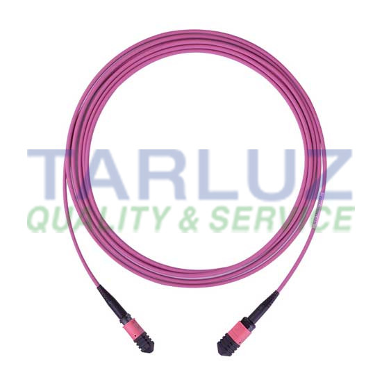
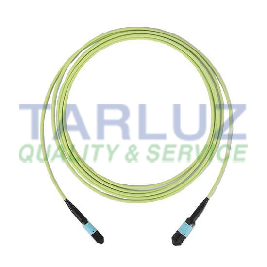
Multi – mode Fiber
Multi – mode fibers, such as OM3, OM4, and OM5, are suitable for short – distance transmissions. The maximum transmission distances for OM3, OM4, and OM5 fibers are approximately 300m, 400m, and 440m respectively. These fibers are commonly used in data centers for connections between servers, switches, and storage devices.
Single – mode Fiber
Single – mode fibers, such as OS2, are designed for long – distance transmissions. They can be used in applications such as metropolitan area networks (MANs) and passive optical networks (PONs), with a maximum transmission distance of up to 10km.
In conclusion
understanding the key parameters of MPO jumpers is crucial for selecting the right jumper for specific applications. By carefully considering factors such as fiber core count, insertion loss, return loss, flame – retardant rating, polarity, and transmission distance, users can ensure the optimal performance and reliability of their fiber – Tarluz optic networks.
Step-Index vs Graded-Index Fiber: A Fundamental Guide to Specialty Optical Fibers
Product Show: Fiber Optical Fusion Splicer